Invoking the RUDRA
A comprehensive guide to building your own Autonomous Robot.
RURA:: ROS-Unified Differential-drive Remote-mode Autonomous-rover
This article is a comprehensive documentation of the autonomous rover that I’m working on and constantly upgrading. In this article, I have tried to cover all the fundamentals, the working theory, the practical implementation, and the optimization concepts necessary to build a differential drive robot from the ground up.
The article is designed in a manner to not only provide you with step-by-step instructions to build the rover but also to develop the essential competency in applied SLAM and autonomous navigation using ROS.
The current version is v3.0. The limited documentation for v1.0 and v2.0 can be found here.
Version 3.0 Upgrades:
- ROS Noetic on Ubuntu 20.04
- Intel NUC i7–7567U, 16 GB DDR4, 1TB M.2 SSD & 256 GB SSD
- YDLiDAR G2 360° LIDAR
- Intelligent DCDC converter to regulate 19v to NUC from 3S LiPo


Table of Contents:

A. Theory — Differential Drive Robots
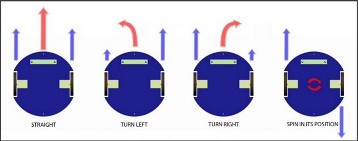
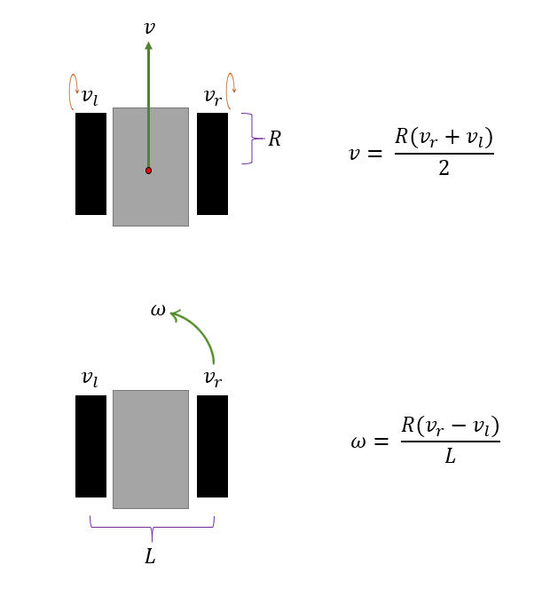
RUDRA is a differential drive robot. This means that the robot’s steering is purely based on wheel velocities. The robot will sway right if the right wheels rotate slower than the left wheels. If the right and left wheels rotate in opposite directions, the robot will spin in its position. This behavior is illustrated in the figure below.
Let’s understand the math behind this type of model. This will help us later in developing the firmware for driving the rudra_base.
For simplicity, let's consider an imaginary robot with just two wheels. The wheel radius is R, and the distance between the wheel centers is L . We need these measurements in meters later in our code implementation. For RUDRA, these values are 0.0675 meters and 0.29 meters.
As seen below, let the individual wheel velocities be vr and vl (rad/s).
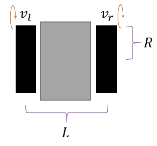
v_l → left wheel velocity (rad/s)
v_r → right wheel velocity (rad/s)
Let’s add a global(map) coordinate frame and define the entities that determine the location and orientation of this imaginary two-wheeled robot.
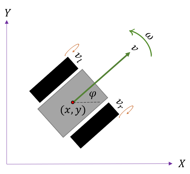
The state of a rover robot is defined by three parameters commonly called the robot's pose. The pose is a vector of size 3 →[x, y, φ]
x → position of the robot on the X-axis (m)
y → position of the robot on the Y-axis (m)
φ → angle of the robot counter-clockwise from the X-axis (rad)
The pose can be manipulated by the 2 commands, the velocities [v, ω]
v → forward velocity of the robot (m/s)
ω → angular velocity of the robot (rad/s)
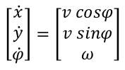
On a side note, notice that we can compute the rate of change in the robot’s pose as follows:
So far, so good. Remember that we can only control wheel (motor) velocities in reality. We need to figure out how to translate the commands [v, ω] to [vr, vl]. There are sophisticated ways of deriving this, and you can watch this lecture to know more.
All we need to know for implementation are the equations discussed below. Try substituting values for v_r and v_l, and you will see how the equations make sense if you are looking for quick intuitions,
If we solve the above equations, we get:
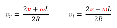
Here, L and R are fixed and known for the given robot, while v and ω are input command velocities. We will discuss more on why it is necessary to consider v and ω as commands in a later section when we discuss ROS Navigation Stack.
Now that we know what the wheel velocities should be, how do we control the motors to set those wheel velocities? The answer is Pulse-width Modulation. Check out the following YouTube playlist on how to control DC motors.
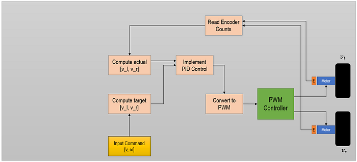
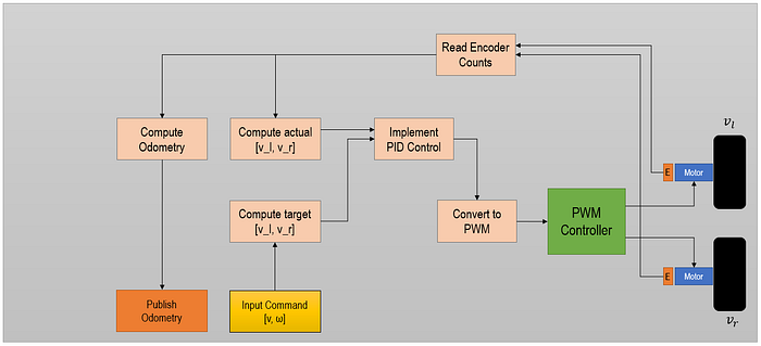
Let’s slowly build our understanding of rudra_base by developing a flowchart as we unpack these details. So far, we know how to calculate individual wheel velocities from command velocities. Then we know we need to convert the velocities to PWM values which a PWM controller will implement to achieve the desired wheel velocities.
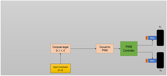
The immediate next challenge is, how do we know the actual wheel velocities? We need a feedback loop. This is where the encoders attached to the motors help us.

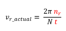
We will discuss in later sections how to count these encoder pulses; for now, we just need to know that the encoders help us count the number of pulses (n) as the motor shaft rotates. By design, we will also know upfront how many pulses (N) one full wheel rotation can give us. N is fixed for a given encoder-motor combination.
If we measure n pulses from the encoder in time, t. The actual velocity of the wheel (say right wheel) can be calculated as follows:
In practice, the actual wheel velocities are not always equal to the target velocities we want the wheel to have. There can be several reasons for this, such as inefficiencies in the motor, errors in PWM computation, the voltage available for the motors, etc.
This difference in actual and target velocities becomes a problem. If both wheels are not spinning at the same speed for a full forward command, the robot will sway right or left and not travel in a straight line. To overcome these issues, we implement a PID controller.
Now, we have a feedback loop in our flowchart.
Now that we have access to encoder counts, could we compute the distance traveled by each wheel?
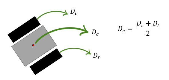
We can compute the distance traveled by each wheel, D_r and D_l, using the following equation.
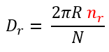
Where R is the radius of the wheel in meters.
Once we know D_r, D_l, and D_c, we can compute our robot's odometry (dead-reckoning).
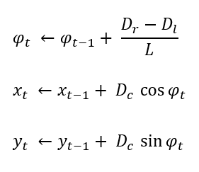
With this new information on odometry, we update our flowchart.
Since our robot is moving on a map. A fixed reference frame in that map will help us locate our moving robot at any given time. ROS expects the robot to publish odometry frame transforms to be able to implement the ROS Navigation Stack. We will discuss the navigation stack in detail later in the article.
The flowchart is now updated for publishing transforms.

B. RUDRA Hardware BOM
Refer to the BOM for all the hardware components.
C. Architecture RUDRA
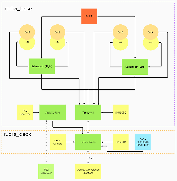
There are several ways to layer the hardware stack in building a ROS-based differential drive. The idea behind the build is centered around Modularity. I wanted the rover to be modular to scale it as needed. For instance, if I wanted to pack more computation power on the rover, I could switch Jetson Nano for a NUC without reworking the entire base and writing new codes. One way of doing this was to isolate the base from the brain.
This requirement drives several hardware choices:
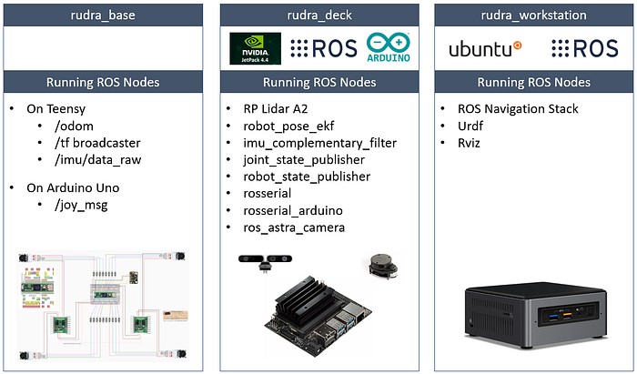
- The sole purpose of the base is to make the robot move based on commands from the brain and send position feedback (transformation and odometry ) back to the brain. The rudra_base would have to perform most of the heavy lifting in pose and velocity calculations. It should have enough bandwidth (buffer size) to send data back and forth without choking. An Arduino Mega would not be able to do this effectively. Also, you will quickly realize that you’ll need a lot more I/O pins. This is why I have a Teensy 4.1 in there. Check this link for a one-to-one comparison of Arduino and Teensy. Now there are several other choices for controller boards, but I chose Teensy because it's Arduino-like. It's easy to program a Teensy using Arduino IDE and Arduino libraries. The form-factor of Teensy is also an important attribute to keep in mind. In the context of the flowchart we have been developing, the rudra_base stack is as follows:

- I also have an Arduino Uno in rudra_base. The plan is to use Arduino for menial tasks such as operating LEDs, PS2 Controler, etc., while the Teensy is doing all the heavy lifting. You’ll later see that Teensy is publishing and subscribing to several topics. Also, there may be Arduino-specific libraries that may not work well on Teensy (future-proofing).
- The Sabertooth motor driver was an interesting choice. This is packed with features, and it offers several ways to control the brushed DC motors. Check this video that explains all the functionality. This inherent flexibility of Sabertooth motor drivers was the key feature based on which I made my decision to use it. It was possible to control all four motors using a single pin on Teensy. This is in line with my plans for a Modular approach. rudra_base has 4 motors and two Sabertooths.
- In RUDRAv1, I integrated IMU6050 with the Jetson Nano. In the spirit of modularity, I have moved the IMU6050 and integrated it with Teensy instead. If I had to use a NUC, I would not have access to I/O pins to integrate MPU6050 with the NUC.
There are some caveats that I had to keep in mind in developing RUDRA. These may not be important to all rover builds.
- The choice of motors and the encoders are important. You need a good drive system that can respond well and predictably to your commands. And the encoders are important to calculate odometry and play a vital role in autonomous navigation. Choose a good motor encoder setup. You can also look for DC brushless motors too. Check out the D6374 motor and ODrive controller. There are plenty of options out there. You just have to look for what works for you. I was comfortable with brushed motors when building this rover, so I went with this option.
- The traction on the wheels is important too. If the wheels are no good and there is slippage, the encoders won't be of much help. Source good wheels.
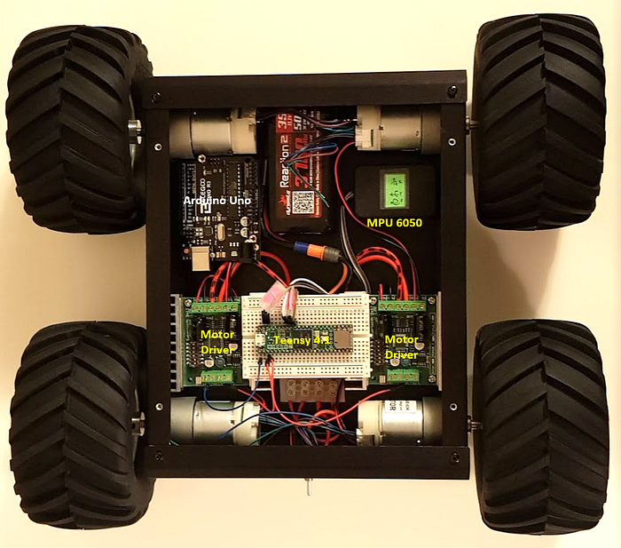
- The MPU6050 is sensitive. All we need from this MPU is the “sense” of direction to fuse with the Odometry. Make sure you mount this well in your assembly. I packed it with a sponge in a small black box. See the picture of rudra_base below.
- Make sure you have good wires that are rated for high amperage. If one of the motors is defective or has high loading, it will draw a lot of current from the Sabertooth. You will likely burn the wires if that's the case. Sabertooth has built-in features to avoid this situation. But your design should consider worst-case scenarios.
D. Software Setup (Ubuntu 20.04)
The Jetson Nano is the Brain of the rover. This will be our Master for implementation purposes. The Teensy and Arduino communicate to Jetson Nano (or, NUC). All the following installations are on the Nano.
- Install Arduino IDE
We begin with Arduino first because we will install Arduino-specific packages to support the serial interface between ROS and Arduino/Teensy once we install ROS.
Note: the following steps are for Jetson Nano. IDE 1.8.15
$ git clone https://github.com/JetsonHacksNano/installArduinoIDE$ cd installArduinoIDE$ ./installArduinoIDE.sh
Reboot the Nano once the installation is completed.
2. Teensy Software Setup
Note that you will have to choose the latest download from https://www.pjrc.com/teensy/td_download.html
Jetson Nano is ARM 32bit. So we will use Linux Installer (ARM 32 bit / Raspberry Pi) and download it to the Downloads folder.
Once you download this file. Copy the Linux udev rules from https://www.pjrc.com/teensy/00-teensy.rules
Note that if you do a Save As from the browser, it might download as a .txt file. You’ll have to find a way to disassociate the .txt from the file before running the below command after cd into Downloads. The file HAS TO BE in *.rules.
The best way is:
gedit 00-teensy.rulesCopy the contents of udev file and save.
Then,
sudo cp 00-teensy.rules /etc/udev/rules.dchmod 755 TeensyduinoInstall.linux64./TeensyduinoInstall.linux64
Follow these steps to set up the Teensy Loader for Ubuntu Linux: https://www.pjrc.com/teensy/loader_linux.html
Follow this awesome tutorial to check if everything is working: https://www.pjrc.com/teensy/tutorial.html
Note: When I copied the udev rules from the webpage to the gedit file, there was an unwanted space at the end of all the copied content. There should not be any extra character or space beside the exact content in the udev file.
3. Install ROS and key packages
I used the Noetic distro for this project. Install ROS and rosdep as detailed in http://wiki.ros.org/noetic/Installation/Ubuntu.
You’ll also need rosserial and rosserial_arduino to interact with Arduino and Teensy.
$ sudo apt-get install ros-noetic-rosserial-arduino$ sudo apt-get install ros-noetic-rosserial
Now that you have installed rosserial_arduino, you’ll have to create ros_lib in the Arduino library folder. (This is why we installed Arduino IDE first)
$ cd <sketchbook>/libraries
$ rm -rf ros_lib
$ rosrun rosserial_arduino make_libraries.py .
Note: do not forget the <space>and the . after libraries.py in the above command line.
At this point, I suggest you perform a reboot.
E. RUDRA Schematic and Wiring
It's time to build the rover. Follow the schematic in the image below to put the base together.
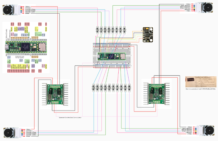
In the end, the build will look somewhat like the below image. If you can avoid the terminal blocks and the breadboard, you will have more room for good wire routing.
F. Power and Batteries
I decided to separate the batteries for the base and the brain to scale the batteries as necessary. The motors are 12v DC which is why I have a 4S LiPo Battery for the motors in the rudra_base.
To power the NUC, I have a 3S LiPo battery connected to mini-Box DCDC intelligent converter which outputs a stable 19v. The LiDAR, Teensy, and the Arduino are powered by the NUC over USB.
If you have a Jetson Nano, all you will need is a 5v power bank.
G. rudra_base Hardware & Software Integration
As well understood at this point, we are using ROS to bring RUDRA to life. For the rest of the article, I’ll assume that you know ROS to the extent that you understand the graph below.
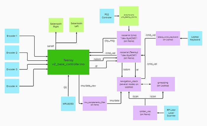
If you find it difficult to understand what this graph summarizes, you have some homework to do. Start here and work your way up to get a good grip on the fundamentals of ROS implementation with C++.
We will unpack each of the hardware and software integration starting with rudra_base layer.
The following computations are going on over the Teensy. Refer to v2_base_controller.ino file as we discuss the following:
- Sending PWM signals to Sabertooths to drive the motors.
- Calculating wheel velocities based on encoder counts
- Pose estimation calculations (x, y, theta)
- Publishing IMU6050 data to /imu/data_raw
- Publishing transforms /tf
- Publishing Odometry data /odom
- Subscribing to /joy_msg coming from Arduino
- Subscribing to /cmd_vel coming from ROS nodes on the network.
1. Setting up Teensy 4.0 for ROS Serial
Teensy uses Arduino-ROS libraries. However, some important changes are required in the Arduino Libraries to make Teensy 4.0 work with ROS.
The first one is the ArduinoHardware.h file. Locate this file in the rosserial_arduino folder in the Arduino Libraries folder. Open the ArduinoHarware.h file and look at line 44. You’ll see an if statement. Make sure there is defined(__IMXRT1062__) in that line, as shown below. If it's not present, edit to add that as shown.
if defined(__MK20DX128__) || defined(__MK20DX256__) || defined(__MK64FX512__) || defined(__MK66FX1M0__) || defined(__MKL26Z64__) || defined (__IMXRT1062__)Without this update, Teensy 4.0 won't communicate over rosserial.
Buffer Size: The second change would be to ros.h file. One way is to copy the ros.h file provided in my GitHub repository and always accompany this ros.h file with the *.ino file you create for Teensy. The other way is to change the standard ros.h file in the Libraries folder. I would not recommend changing the ros.h in the Arduino Libraries folder simply because if you end up using an Arduino UNO or Mega, the changes you make will not work. Simply keep a ros.h file in the same folder as the *.ino file you are going flash on to Teensy.
Changes in Line 12>>#else typedef NodeHandle_<ArduinoHardware, 25, 25, 2048, 2048> NodeHandle;
This set our NodeHandle to have 25 Publishers, 25 Subscribers, 2048 bytes for the input buffer, and 2048 bytes for the output buffer. 25 Publishers and Subscribers each are way more than enough for this project, but if you might need more of these PubSubs, you know what to do! I hope the advantage of using Teensy4.1 over Arduino Uno or even Mega is becoming apparent.
Now that we have the environment setup, let's dive into the codes.
2. Motor Control using Teensy and Sabertooth
Motors: 12V, 58RPM 60:1 Gear Motor w / Encoder (x4)
Motor Driver: Sabertooth Dual 12A 6V-24V Regenerative Motor Driver (x2)
I chose a 12V motor. I liked the idea of having enough power to drive the monster truck wheels around on irregular terrain. I did not do any math; I just went with 12V motors. You could downsize to 6V or upgrade to 24V with this Sabertooth.
Pay attention to the Motor Stall Current in the spec sheet. Here is the spec sheet for my motors: https://www.robotshop.com/media/files/pdf2/049-rb-cyt-83.pdf
You'll notice that the stall current is 2.7A. The Motor Driver you choose will need to accommodate that draw current for a stalled motor. Also, remember that you will have typically 2 motors connected to a single driver. Add a generous amount of safety margin. This Sabertooth is rated for 12A, which is amazing and pretty much what we will need on the project. You might be tempted to get one of these — https://handsontec.com/dataspecs/module/L298N%20Motor%20Driver.pdf — which you will often see being used in a lot of DIY projects. Take a look at the max peak current in the spec sheet. Its 2A. That’s not going to work for these motors. I learned it the hard way! Lol!
Also, ensure that the wires you use are rated for peak currents, and you might not have to deal with a fire hazard.
I hooked up the left motors to the left Sabertooth and the right motors to the right Sabertooth. When connecting to the Sabertooth, I switched the polarity of one of the motors so that I had to only worry about sending positive PWM values for the forward motion of the robot, and both the left and the right motors would rotate clock and anti-clockwise accordingly to have all the wheels turn in the forward direction.
Sabertooth offers several methods by which you can control the motor. If you have only two motors for a differential drive, the Sabertooth has a special method that can implement that with ease. However, RUDRA has 4 motors, and the motors are not hooked up to the Sabertooth in a way this special method can be utilized. Feel free to explore those methods here:
I went with the Packetized Serial Mode (Mode 4, Page 15 in the Manual). This method is awesome and utilizes just one Serial pin on the Teensy to control 4 motors on two Sabertooth. This is how it works:
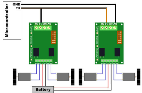
Packetized Serial uses multi-byte TTL-level serial commands to set the motor speed and direction. Packetized serial is a one-direction-only interface. The TX1 of Teensy is connected to S1. The RX1 is not connected to the Sabertooth. Because of this, multiple Sabertooth 2x12 motor drivers can be connected to the same serial TX1.
Packetized Serial operates with an 8N1 protocol — 8 data bytes, no parity bits, and a one-stop bit. The baud rate is set at 9600 baud from the factory. We will keep this as is. This value can be changed by sending the proper baud rate selection packet once the unit has powered on. Changed baud rates will be active after a power cycle. Once you set it, it stays that way until you change the rate again.
Packetized serial uses an address byte to select the target device. Address bytes are set by dip switches 4, 5, and 6.
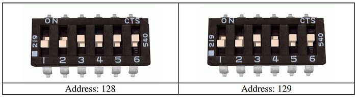
The above is what the dip switches should look like on your Left and Right Sabertooths.
Once you have set the dip switches, you do not have to worry about how the rest of the communication happens between the Teensy and the two Sabertooths. The Arduino library Sabertooth.h will take care of this for you. However, you must know that the PWM value -127 is the full reverse, 0 is the full stop, and +127 is the full forward for each motor.
Given that I have switched the polarity when connecting the motors, I now do not have to manage the direction of rotation of the individual motors actively.
The Sabertooth Setup for Arduino is available at https://www.dimensionengineering.com/info/arduino. We will use these libraries for Teensy.
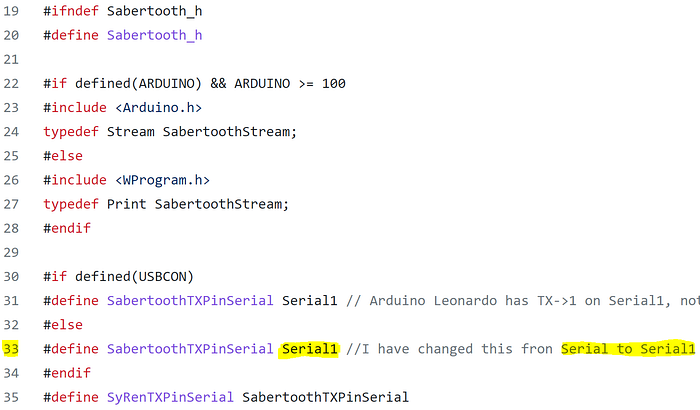
Remember that Teensy is communicating with the Jetson Nano over ros-Serail0. We need to explicitly ensure that the Serial 1 (TX1) on Teensy is dedicated to Sabertooth to avoid conflicts with ROS. I did this by modifying line 33 of Sabertooth.h file. Changed Serial to Serial1.
At this point, you would’ve connected 4 motors to the Sabertooths and connected the Serial1 of teensy to S1 of both Sabertooth drivers.
Now, let's write a simple code to run the motors and see if it all works.
Flash the above code onto the Teensy. Power the motors.
The direction of rotation of the wheels should be all forward or reverse or fully stopped based on the code above. If one of the wheels is spinning in the opposite direction, then change the polarity of the motor connection at the Sabertooth.
3. Teensy and the Encoders
Encoders are important. They can provide us with the actual wheel velocities based on which we can do 3 important things:
- Calculate actual wheel velocities:
- Implement PID control: THIS is a good paper to start. It will give you a good overview of a differential drive robot and how to implement a PID control.
- Calculate the odometry/current pose of the robot — x, y, theta
You MUST review this: https://www.pjrc.com/teensy/td_libs_Encoder.html
The first experiment we need to do is measure encoder counts. Depending on the motor, the gear ratio, and the encoder type, the encoder count for one full wheel rotation can vary. We could work out the math or run some experiments to determine the encoder's count for one full wheel rotation. We do not need ROS for this. I suggest writing a simple code based on https://www.pjrc.com/teensy/td_libs_Encoder.html print the raw encoder counts to the serial display in Arduino IDE. Note that all the pins on Teensy 4.1 are interrupt pins. If you have a different microcontroller board, you may need to find those relevant pins from the schematic. You should run the experiment several times and average the encoder counts. Mark the wheel at 0 and turn the wheel 360 degrees, and record the encoder count. This count is our count per revolution (N), a constant we will use when calculating actual wheel velocity.
We will be using the same Teensy Encoder libraries from the PJRC .
I have annotated the code to be flashed onto the Teensy and you can read thru to understand how the encoder counts are used to calculate actual velocities.
On line 317, I’m starting a timed loop with LOOPTIME variable. You can vary this based on your needs. I found that 100ms was suitable to have PID work well in this same loop.
Every 100ms, I accumulate encoder counts at each wheel and use the following equation to calculate wheel velocities.
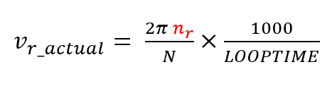
Where n_r is the encoder counts within a time frame of LOOTIME milliseconds.
We have discussed why we need PID control and how it works in the Theory section. In the implementation, once we have calculated the wheel velocities, we invoke the following function:
The kp_, ki_, and kd_ are constants that you will determine based on your PID tuning exercise. The values you arrive at can be completely different than what I have because of differences in the build, the motor performance, motor drive, etc. You have to do this exercise to determine values specific to your robot.
One very important point to implement is zero out the Integral Error if the robot stops. The integral error is accumulated over time, and if it's not zeroed out when the robot comes to a standstill, the next time you time to move it, the integral error accumulation kicks in, and the robot accelerates unexpectedly.
I have a separate function to bring the robot to stop, and I zero the Integral Error in that function. See below:
The other and the most important function is Odometry calculation. As discussed in the Theory section, the Odmetery information lets the navigation stack determine where the robot is on the map.
The Odometry computation is implemented in the Teensy *.ino file between lines 478 to 508. You will recall the equations from the Theory section in understanding this block of code.
4. Teensy and the MPU6050
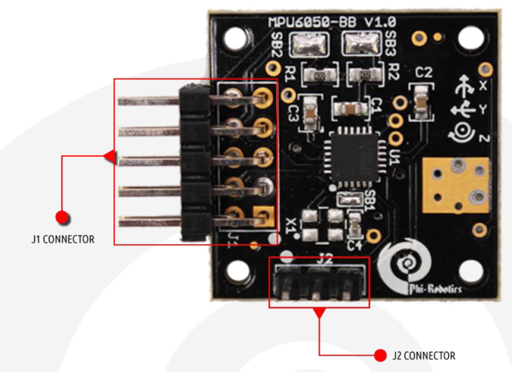
The MPU6050 is a popular six DoF accelerometer and gyroscope (gyro). Check out the documentation here: https://github.com/AdarshGouda/RUDRAv3/blob/main/IMU-Teensy/documentation-h-elc-sen-imu-3-ag/MPU6050-BBManual.pdf
I have used the implementation detailed in the following video to use IMU in RUDRA. The IMU6050 is implemented on Jetson Nano in the video, but I have Implemented it on Teensy.
Notice the X, Y, and Z directions on the PCB. In our implementation, X is the forward direction. This implies that the gyro direction about Z-axis determines theta.
The IMU is used for Odometry too. Yes! The econders help us with the odometry, but they are not 100% reliable. Factors like uneven surfaces and slippage of wheels can inflate or deflate the Odometery calculations. We need another source to “fuse” and correct the Odometry.
Odometry from the wheel encoders is unreliable, and odometry from IMU tends to drift. We need to combine these two in RUDRA to arrive at a good Odometry estimation.
We will use the Extended Kalman Filter (EKF) package available in ROS to fuse the Odometry from encoders with that from IMU to compute better estimates.
To know more about EKF, please watch these videos.
Note that on line 492, I have implemented a simple complementary filter which does help. But if we use the EKF package in ROS, this will not be necessary.
The complete sketch to be flashed on Teensy is as below.
Note: Make sure you place the modified ros.h file with the above *.ino file before flashing.
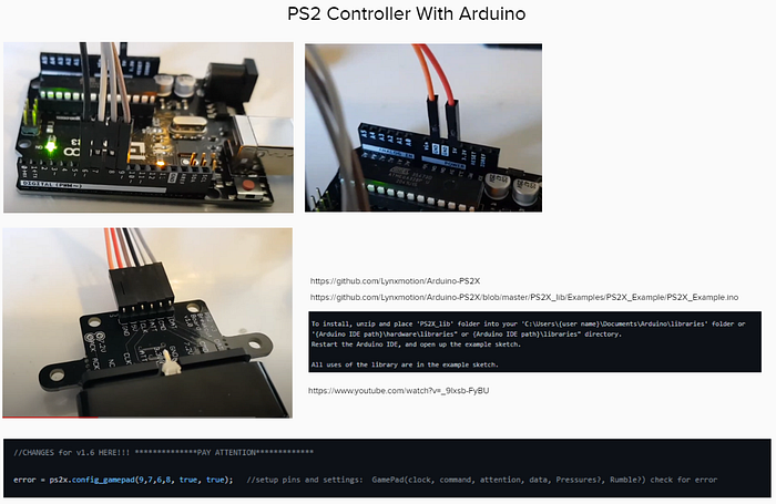
5. Arduino & PS2 Controller
As mentioned before, there is also an Arduino Uno in the rudra_base connected to the PS2 receiver. The *.ino file flashed on Arduino is as below.
I have used the PS2 controller here to take control of rudra_base when needed. I have created a custom message in ROS called /joy_msg to integrate the PS2 with ROS.
The rover has a manual override that can be achieved by pressing the “mode” button on the PS2 controller. The rover is then completely under your control, and you can have some fun with it. This feature is particularly helpful when generating the map, which the navigation stack will later use.
H. ROS-on-RUDRA
- ROS Primer
The following playlist is probably all you’ll need to get started with ROS.
2. ROS Setup for RUDRA
Refer to the image below explaining the ROS setup for RUDRA navigation.
3. rudra_workstation
You could set this up on your Ubuntu laptop or a NUC. I plan to use a NUC for rudra_deck to replace jetson nano in the future. But for now, I have the NUC as my workstation. This is how I set it up:
If you are using NUC for rudra_deck. Follow the same steps above to set it up.
We will SSH in on rudra_deck from rudra_workstation.
4. rudra_deck
Previously, I had a Jetson Nano as the hardware platform for rudra_deck implementation. Jetson Nano works on Nvidia’s Jetpack. Follow the installation steps in the below YouTube link to set up your Jetson Nano for ROS.
Please note that Jetson Nano has its own packages that work on Jetpack. The packages and libraries that can be easily set up on a Ubuntu machine may not be compatible with Jetson Nano. Jetson Nano has a learning curve, and you will have to be familiar with its nuances before using this on the rudra_deck. Jetpack runs on top of Ubuntu 18.04 and ROS melodic. The ROS Noetic distro is not yet stable on Jetson Nano at the time of writing this article. Such limitations you have to work with when using Nano or the Raspberry Pi. A NUC is a lot better since you can install the latest full Ubuntu OS, and you won't have to worry about the compatibility of various packages and software. However, the NUC runs on 19V and Jetson Nano on 5V. Source your power supply accordingly.
Check out these tutorials for setting up your Jetson Nano:
Once you have set up your Nano, see the following video to setup ROS:
For the RUDRAv3 version, I switched to a NUC as an upgrade. Perhaps Jetson Nano will suffice in terms of computation. However, I upgraded to a NUC to experiment with different computation-intensive packages. Nonetheless, I am not using any GPIO Pins on Jetson Nano. All connections are USB/UART-based, which means I have the flexibility to switch between a Nano or a NUC depending on my needs.
Note that Jetson Nano works efficiently at 5V@4A, and you can use a power-bank to run it. NUC requires 12–19V DC. I use a Dewalt 20v battery with a DCDC intelligent regulator to maintain 19V.
5. Introduction to Navigation Stack
We will be using ROS Navigation Stack Package to navigate our RUDRA autonomously.
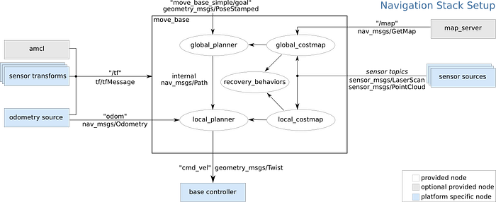
The navigation stack assumes that the robot is configured in a particular manner to run. The diagram above shows an overview of this configuration. The white components are required components that are already implemented, the gray components are optional components that are already implemented, and the blue components must be created for each robot platform. The pre-requisites of the navigation stack, along with instructions on how to fulfill each requirement, are provided in the sections below.
We will modify the above stack to RUDRA’s stack so that it's easier to understand.
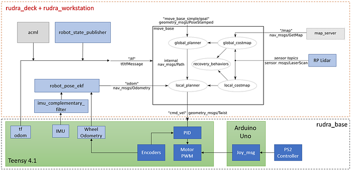
All our discussions and flowcharts culminate in the above architecture. I hope it's all making sense now.
6. Coordinate Frames
This post on the ROS wiki has everything you need to understand why coordinate frames are important.
Below are the standard coordinate frames for a basic two-wheeled differential drive robot.
- The red arrows represent the x-axes
- The blue arrows represent the z-axes
- The green dots (into the page) represent the y-axes.
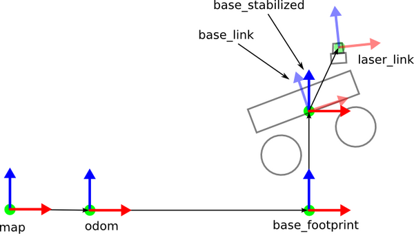
- map frame has its origin at some arbitrarily chosen point in the world. This coordinate frame is fixed in the world.
- odom frame has its origin at the point where the robot is initialized. This coordinate frame is fixed in the world.
- base_footprint has its origin directly under the center of the robot. It is the 2D pose of the robot. This coordinate frame moves as the robot moves.
- base_link has its origin directly at the pivot point or center of the robot. This coordinate frame moves as the robot moves.
- laser_link has its origin at the center of the laser sensor (i.e. LIDAR). This coordinate frame remains fixed (i.e. “static”) relative to the base_link.
If you have other sensors on your robot, like an IMU, you can have a coordinate frame for that as well.
How can we automatically convert data that is published in one coordinate frame to equivalent data in another coordinate frame? For example, suppose we have an object at coordinate (x=3.7, y=1.23, z = 0.0) in the map coordinate frame. We want to navigate the robot to this object. What is the object’s position relative to the base_link coordinate frame?
Fortunately, ROS has a package called tf to handle all these coordinate transforms for us.
For coordinate frames that don’t change relative to each other through time (e.g. laser_link to base_link stays static because the laser is attached to the robot), we use the Static Transform Publisher.
For coordinate frames that do change relative to each other through time (e.g. map to base_link), we use tf broadcasters and listeners. Many ROS packages handle these moving coordinate frame transforms for you, so you often don’t need to write these yourself.
For RUDRA, we have the following Frames and Transforms —
Static: /base_link to /laser; /base_link to /imu_link
Dynamic: /base_link to /odom
Note that RUDRA will always be in contact with the ground and is not expected to make jumps. Therefore, the base_footprint is excluded from the equation.
Handling Static Transforms:
There are several ways to publish transforms. The easiest way to handle Static Transforms is as follows-
- URFD: define the joints and links in the rudra.urdf file
- Launch robot_state_publisher node. This node will take care of all the Static transforms for you. However, ensure that the frame_id’s match the link names in the URDF file when publishing msgs.
Handling Dynamic Transforms:
The only dynamic transform is the /odom frame broadcasted from Teensy. You’ll see in the *.ino file to be flashed on Teensy.
7. RUDRA Integration
Now that we have covered pretty much everything about the theory and setup of RUDRA, it's time to put the pieces together to make them work as a whole.
Step 1: Setup rudra_base
Flash the following file on Teensy. (Keep the modified ros.h file together with this file)
Flash the following file on Arduino.
Step 2: Setup rudra_deck
Follow the steps in this separate article.
Step 3: Setup rudra_workstation
Follow the steps in this separate article.
8. RUDRA Tandav — Let’s dance!
- Bare minimum RUDRA launch:
SSH into the RUDRA from your workstation.
ssh NUCname@IPaddressOnce logged into RUDRA thru ssh. launch the following launch file. Note that you need to make sure the ROS MASTER is launched. If the ROS MASTER is rudra_workstation, make sure you run roscore on the rudra_workatation before trying the below launch file. If the ROS MASTER is the NUC on RUDRA, you do not have to run roscore, the launch file will take care of this.
source ~/rudra_ws/devel/setup.bashroslaunch rudra_deck rudra_bringup_noLIDAR.launch
On rudra_workstation, run the teleop_key node to control the RUDRA. If its not installed, then:
sudo apt-get install ros-noetic-teleop-twist-keyboardOnce installed, run the following node and use your computer keyboard to control the RUDRA.
rosrun teleop_twist_keyboard teleop_twist_keyboard.pyPair the PS2 Controller. If you press the SELECT button on the PS2 Controller, the RUDRA will dissociate itself from the ROS /cmd_vel commands and switch to /joy_msg commands which mean that you should be able to control the RUDRA via the controller. If you press SELECT again, the RUDRA switches back to /cmd_vel commands, and you can use the keyboard to control the RUDRA, and now the PS2 Controller won't work!
At any point in time if the ssh seems to be non responsive try the following command before trying anything else.
sudo systemctl restart sshd9. SLAM and Navigation
SLAM is the process of map building. You will need to localize the robot to map its surroundings. Localization is achieved by AMCL, and mapping is achieved by gmapping package.
Once the map is saved. We can then use the map to autonomously navigate the robot on the map while actively avoiding obstacles.
Follow this separate article for SLAM and Navigation: